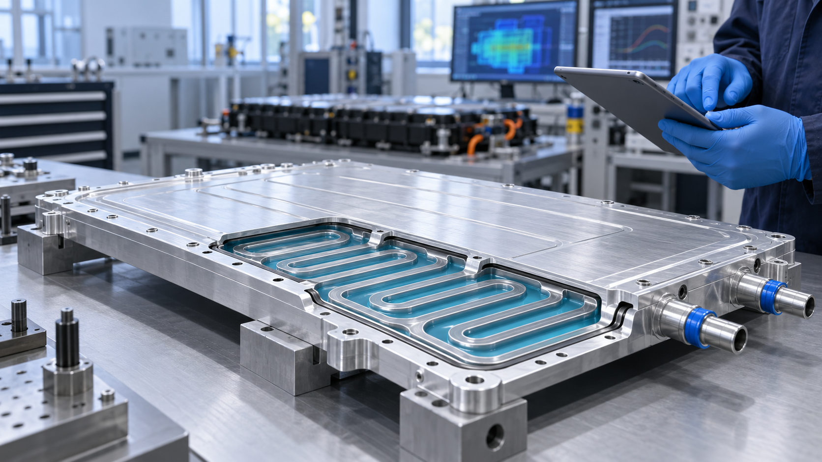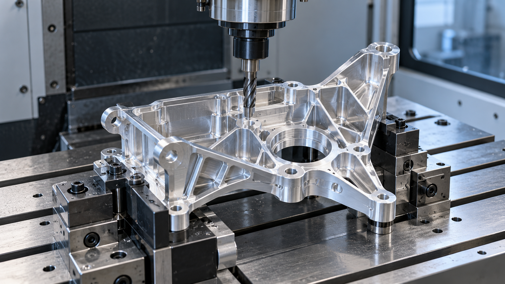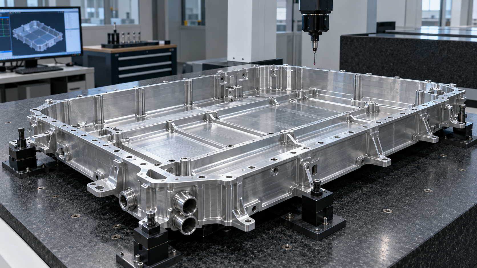
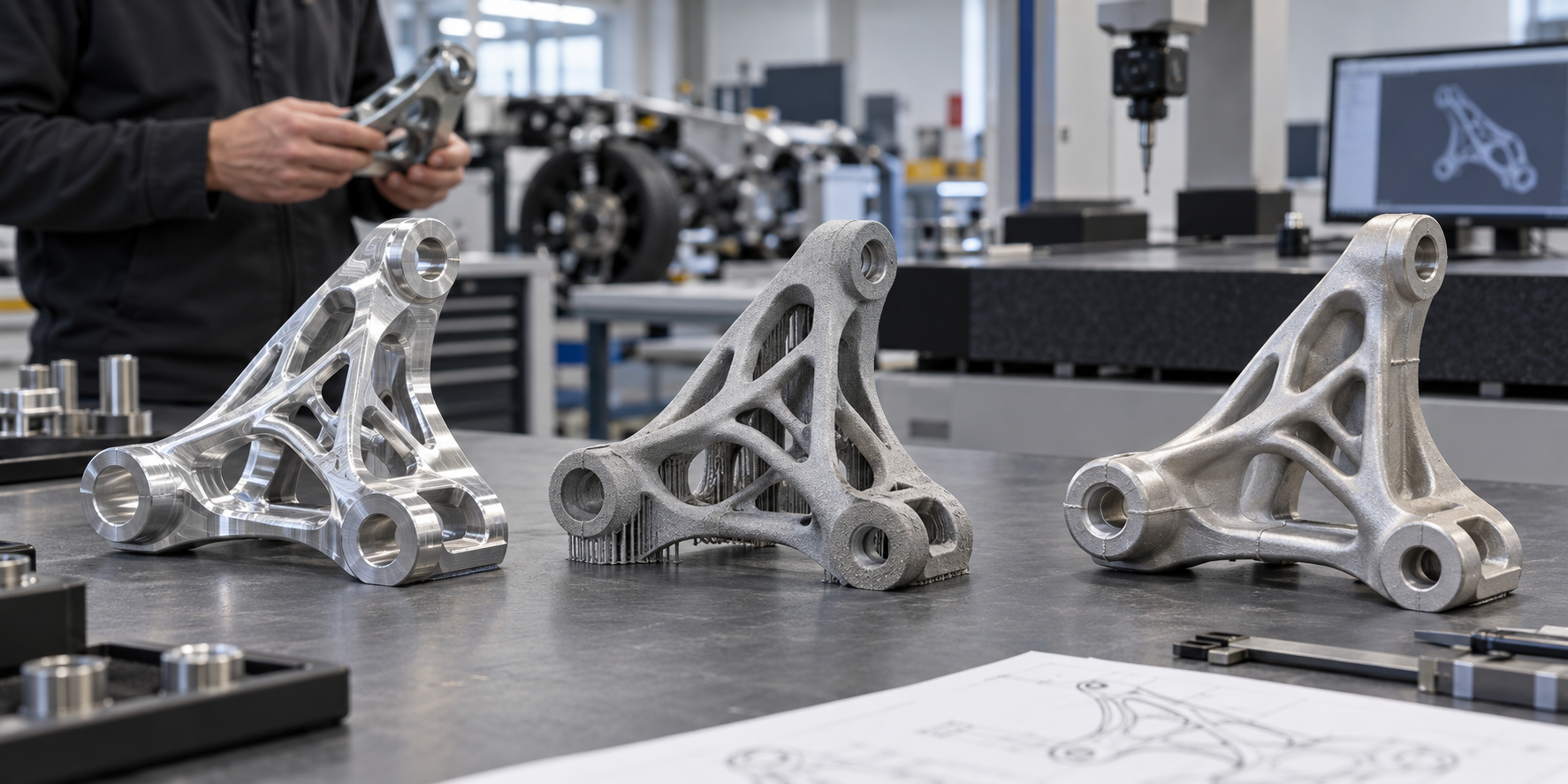
A lightweight automotive prototype is not successful merely because it weighs less. It must answer a defined engineering question without hiding the risks that will matter in the vehicle or in the intended production route. A billet-machined bracket can prove fit and load-path assumptions quickly, a metal additive version can expose the value of internal channels or topology-optimized geometry, and a cast prototype can reveal draft, wall-thickness, feeding, distortion, and finishing issues. Those parts may share one CAD envelope while representing very different evidence.
This guide gives engineering and sourcing teams a practical way to choose among CNC machining, metal additive manufacturing, and casting for a lightweight automotive component. The objective is not to name one universal winner. It is to match the process to the prototype question, document the gaps between prototype and production, and request the inspection and validation records needed for a defensible decision.
1. Define the decision before choosing the process
Start by stating what the next part must decide. A packaging prototype may need stable external geometry and representative interfaces. A functional prototype may need correct material condition, load paths, threads, bearing seats, sealing faces, and surface protection. A process prototype may need casting-like wall transitions, additive build orientation, realistic residual stress, or the same joining sequence expected in production. Mixing these goals creates expensive parts that answer none of them clearly.
Classify the evidence required in four groups: geometry, material, process, and vehicle-level function. Geometry evidence covers datums, interfaces, envelope, clearance, and assembly. Material evidence covers alloy condition, anisotropy, heat treatment, and surface state. Process evidence covers defects, residual stress, distortion, machinability, joining, and repeatability. Vehicle-level evidence covers the loads, temperature, corrosion, vibration, crash, sealing, or durability conditions relevant to the component. Not every prototype must cover all four groups, but the omissions should be deliberate and visible.
Recent automotive lightweighting research treats mass reduction as a multi-objective problem involving safety, durability, NVH, thermal management, manufacturability, cost, and life-cycle effects. That is the right starting point for process selection. A lighter geometry that cannot be inspected, joined, protected, or economically transitioned is not yet a better component.
2. Choose billet CNC when geometry and interfaces lead
CNC machining from billet is often the clearest route when the immediate question is dimensional: Will the part fit, locate, seal, articulate, or carry load through the intended interfaces? It supports controlled datums, machined bores and faces, threaded features, and material conditions that are familiar to design and inspection teams. It also avoids dedicated forming tooling, making design changes easier during early iterations.
The limitation is fidelity to the eventual process. A machined billet does not reproduce cast porosity, solidification behavior, forged grain flow, additive anisotropy, molded fiber orientation, or production wall economics. It may also require temporary access, thicker local stock, or geometry changes that are unnecessary in the final process. Record those substitutions on the drawing and in the test report. Otherwise, a passing billet part can be mistaken for proof that the production process and component are qualified.
Use automotive CNC machining when accurate interfaces, short iteration loops, representative bulk material, or fixture and assembly learning matter more than reproducing the final forming route. Ask the supplier to identify inaccessible features, setup-sensitive relationships, minimum practical radii, tool-reach constraints, and any surfaces that need additional stock for later finishing.
3. Choose metal AM when geometry earns the qualification burden
Metal additive manufacturing becomes compelling when the lightweight concept depends on features that subtractive machining or conventional tooling cannot reproduce efficiently: internal channels, lattice regions, part consolidation, highly organic load paths, or very low-volume complex forms. It can preserve a topology-optimized concept with less geometric compromise and can combine build, support removal, heat treatment, and finish machining into a useful development route.
Geometric freedom is not qualification evidence. Historical research in the source pool on additively manufactured electrical-machine components emphasizes reproducible material-property windows, interface integrity, dielectric or thermal performance where relevant, and component-level qualification. Build orientation, support strategy, powder and machine history, heat treatment, surface condition, and machining allowance can all affect the result. Critical holes, sealing faces, and bearing interfaces commonly still need controlled machining and inspection.
For automotive work, define the consequence of failure and the acceptance plan before ordering the build. Ask which properties are supported by coupons, which require witness specimens built with the part, and which must be verified on the component. If the design cannot justify the extra controls with functional value, a simpler process may produce stronger evidence sooner.
4. Choose casting when production behavior must be represented
Casting is the stronger prototype route when the engineering decision depends on cast wall transitions, ribs, bosses, cores, parting lines, feeding, shrinkage, porosity risk, heat treatment, or production-like machining stock. It becomes especially relevant as a design approaches bridge or series production and the team needs to learn whether the lightweight geometry is compatible with a realistic mold and solidification strategy.
A recent thin-wall automotive demonstrator study linked topology optimization with casting-aware redesign, local shape optimization, and casting simulation. The lesson for buyers is practical: the topology result is a starting structure, not a released casting. Minimum wall thickness, core removal, local stress concentration, filling, and defect risk must be reviewed together. Magnesium research adds corrosion protection, alloy choice, recyclability, and route-specific constraints to the decision.
Different casting routes answer different questions. Sand casting can support low-volume learning with comparatively flexible tooling but may differ from high-pressure die casting in surface, wall capability, porosity mechanisms, and dimensional behavior. A cast prototype should therefore state which production assumptions it represents and which it does not. Do not accept “cast material” as a sufficient description of process equivalence.
5. Compare the routes against the same evidence matrix
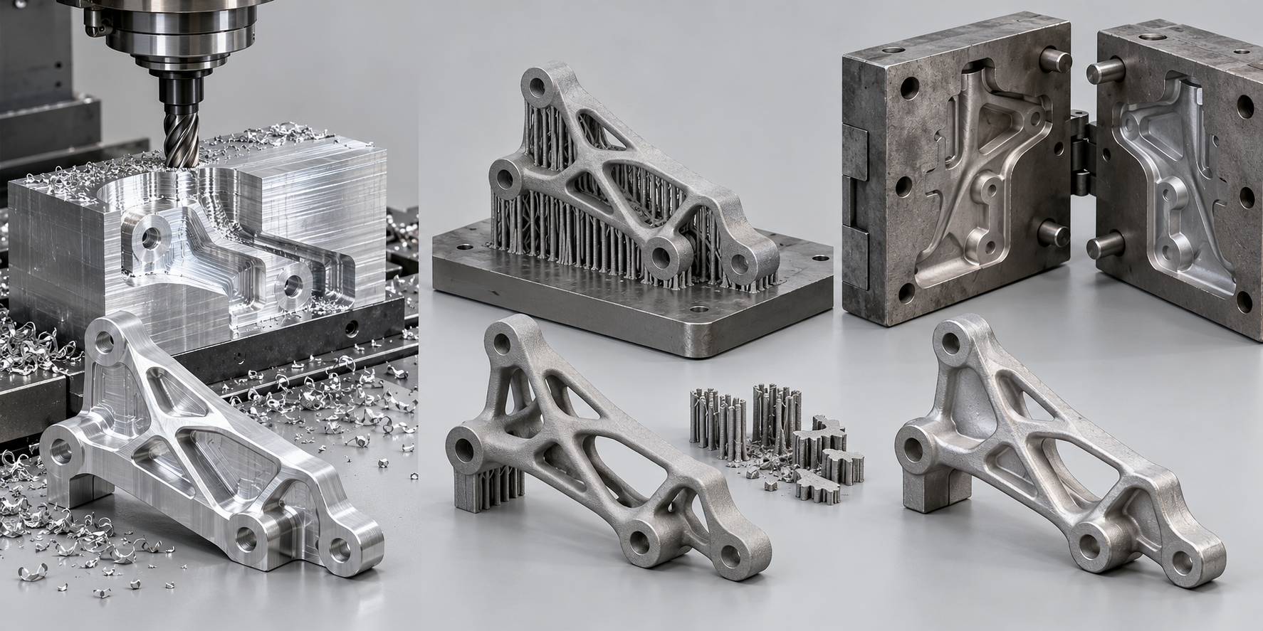
Compare process routes against the same functional requirements while keeping each route's production gap visible.
| Decision factor | Billet CNC | Metal AM | Casting |
|---|---|---|---|
| Best early question | Fit, datums, interfaces, assembly, accessible load paths | Geometry enabled by channels, consolidation, or organic forms | Wall, rib, core, filling, shrinkage, and production-route behavior |
| Typical gap to production | No forming defects or production material flow | Build-specific properties, supports, heat treatment, and finish machining | Prototype tooling and casting route may differ from series tooling |
| Key supplier evidence | Setup plan, material record, dimensional report, finish-machining notes | Build orientation, process record, heat treatment, witness testing, CT or NDT plan where justified | Tooling concept, simulation assumptions, defect controls, machining and inspection plan |
| Common selection error | Treating a billet pass as proof of production-process capability | Selecting AM for novelty without a geometry or volume reason | Ignoring route differences, corrosion, porosity, or machining stock |
Use the matrix as a discussion framework, not a price table. Cost and schedule depend on geometry, material, quantity, inspection, finishing, and tooling assumptions that must be quoted for the actual project. A staged plan is often stronger than forcing one route to answer every question. For example, an early CNC part can close packaging and interface risk, followed by an AM or cast process prototype for material and manufacturing validation.
The historical comparison of conventional aluminum fabrication, metal powder-bed fusion, and composite material extrusion for an automotive brake-pedal case also shows why environmental conclusions cannot be separated from process and functional assumptions. Likewise, component-level evaluation of an aluminum-matrix-composite damper found that geometry, processing route, ductility, stress concentration, surface engineering, and application-relevant testing need to be evaluated together. Material datasheets alone do not settle the process choice.
6. Build a prototype validation matrix before the RFQ
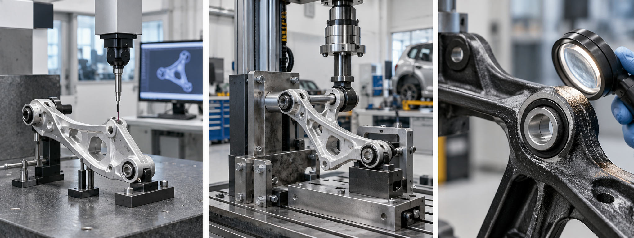
Map geometry, load, material, surface, and interface claims to evidence at the correct test level.
Create one row for each critical requirement and columns for the prototype route, production route, expected difference, measurement method, sample condition, acceptance rule, and owner. Include dimensions and GD&T, mass, stiffness, proof or fatigue loads, thermal exposure, corrosion protection, joining, sealing, surface texture, and post-process condition only where they matter to the component. Identify destructive tests so the required sample count is visible before quotation.
Separate verification from validation. Verification asks whether the supplier built the prototype to the released definition. Validation asks whether that definition performs in the intended use. A CMM report can verify dimensions but cannot validate a suspension load case. A coupon can characterize material but may not capture a thin wall, stress concentration, interface, or local finish. A useful plan maps each claim to evidence at the correct level.
Also define change control. Record CAD and drawing revisions, material specification, process route, heat-treatment condition, surface treatment, and inspection program. If a prototype switches from billet to AM or casting, reopen the requirements affected by the switch rather than carrying the earlier pass result forward automatically.
7. Send an RFQ package that makes tradeoffs visible
A comparison-ready RFQ should include the 3D model, controlled drawing, target quantity, intended prototype use, candidate and production materials, critical datums and interfaces, loads and environments, surface and joining requirements, inspection expectations, and the production process being considered. Mark features that may change and explain whether the supplier may propose alternate radii, wall transitions, machining stock, or split lines.
Ask every supplier to return the proposed route, assumptions, geometry changes, process-to-production gaps, inspection plan, and required customer inputs. This creates comparable answers and prevents a low headline quote from concealing omitted heat treatment, finishing, tooling, inspection, or testing. Autoprototypes' broader automotive manufacturing services can support discussions across machining, tooling, molding, casting, additive routes, and finishing without assuming that one route fits every design.
To scope a lightweight automotive prototype, send the engineering team the CAD model, drawing, target quantity, intended production route, critical interfaces, material condition, and validation requirements. The next step is a manufacturability review that identifies candidate processes, the evidence each route can provide, and the remaining gaps that should stay explicit before a quotation or build is released.
Article information
- Author:
- Going Rapid Engineering Team
- Published:
- Updated: