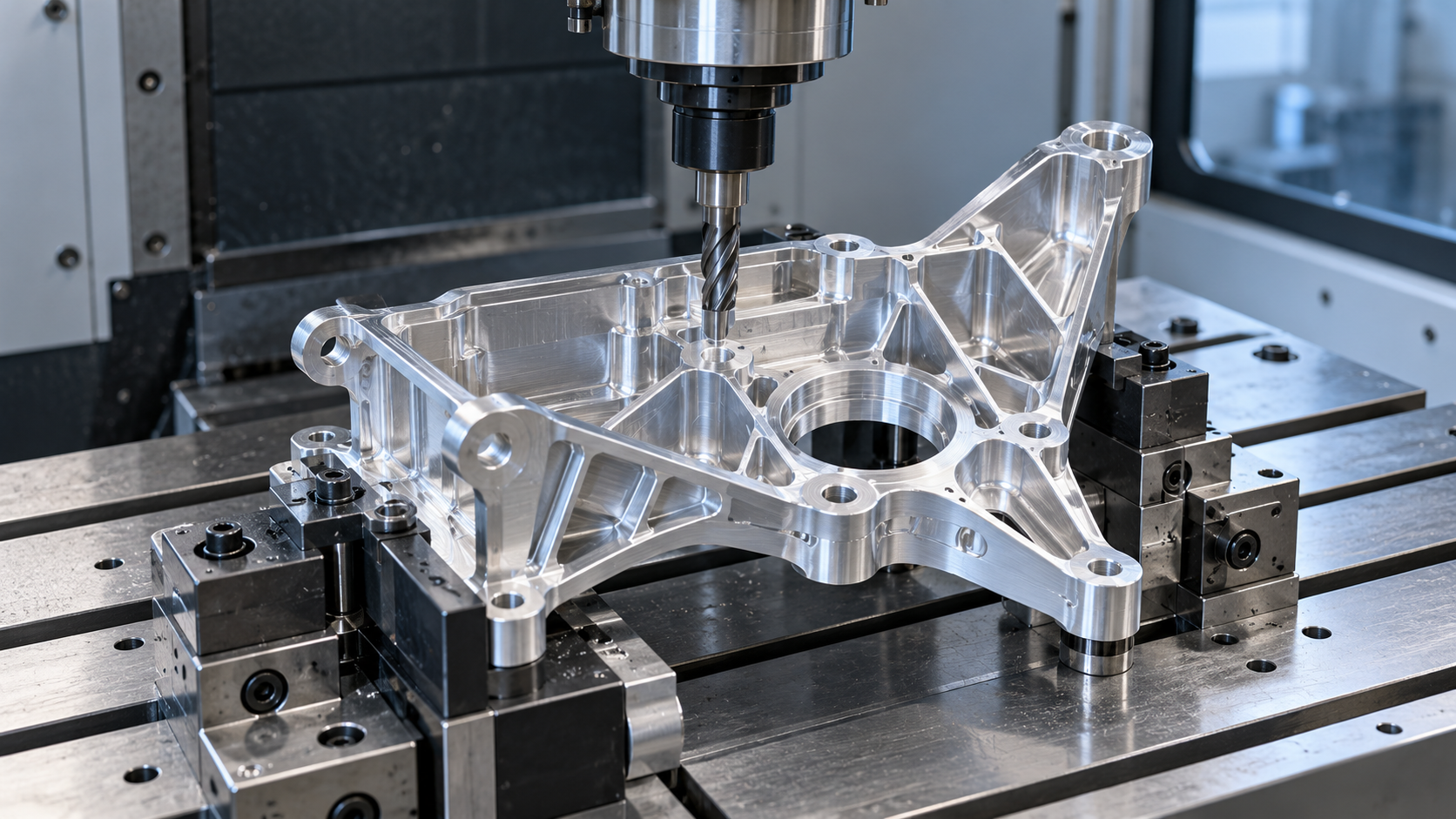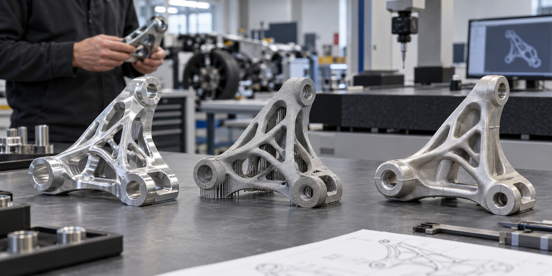
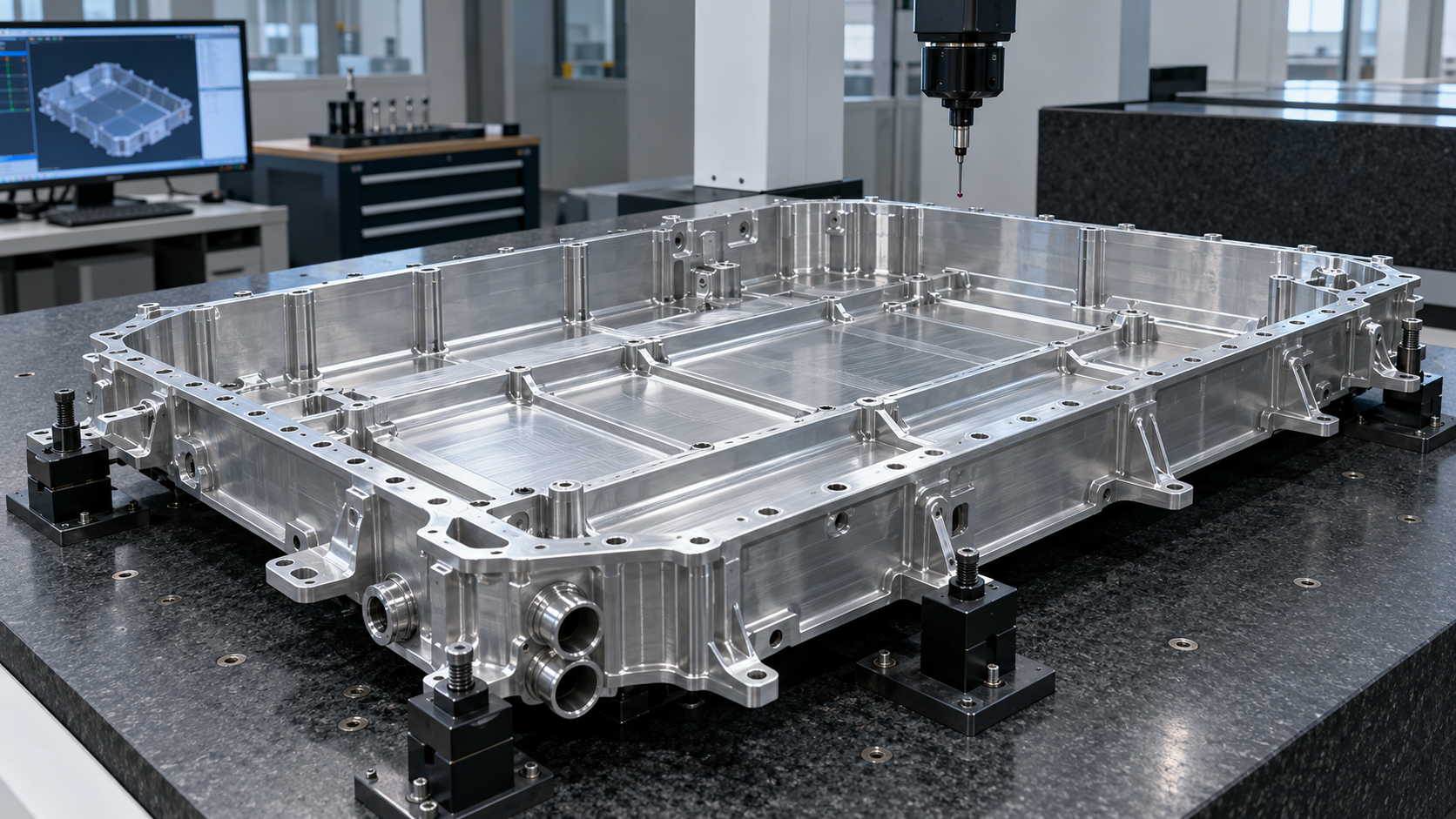
An EV battery enclosure prototype is not validated simply because it matches the CAD model or survives a dimensional inspection. The enclosure is simultaneously a structural part, an environmental barrier, a mounting system, and often part of the thermal-management architecture. A useful prototype program therefore has to connect machining decisions with assembly, sealing, mechanical loading, and repeatable inspection.
The most effective approach is to define the validation question before releasing the part for manufacture. Is the prototype intended to confirm package space, gasket compression, coolant-channel integrity, impact behavior, or a production inspection strategy? The answer determines the material condition, machining route, measurement plan, and test sequence. This guide gives automotive engineers and sourcing teams a practical framework for EV battery enclosure prototype validation without assuming that one test result proves the whole design.
1. Translate vehicle requirements into prototype evidence
Start with a requirement-to-evidence matrix. Vehicle-level standards and regulations describe safety outcomes, but a prototype purchase order must convert those outcomes into measurable part and assembly characteristics. ISO 20653 addresses degrees of protection for road-vehicle electrical enclosures against foreign objects, access, and water. UN Regulation No. 100 provides a broader regulatory context for rechargeable energy storage system safety. These documents should inform the validation plan, but the applicable edition, market, vehicle class, and approval path must be confirmed by the responsible compliance team.
For the enclosure itself, separate the requirements into four groups:
- Geometry: mounting datums, flange flatness, hole position, cover alignment, connector interfaces, and clearance to cells or modules.
- Sealing: gasket land width, groove geometry, surface condition, fastener pattern, vent interfaces, welds, cast walls, and coolant passages.
- Structure: stiffness, local intrusion, joint retention, load paths, permanent deformation, and protection of the cell volume.
- Verification: measurement method, fixture condition, test pressure, stabilization time, environmental state, acceptance rule, and required records.
A prototype does not need to answer every production question. It does need a declared purpose. A packaging prototype may be acceptable in a substitute alloy, while a sealing or impact prototype normally needs representative material, joints, interfaces, and assembly conditions. Record any difference between the prototype and intended production design so reviewers do not treat a partial demonstration as full validation.
2. Freeze datums and sealing interfaces before machining
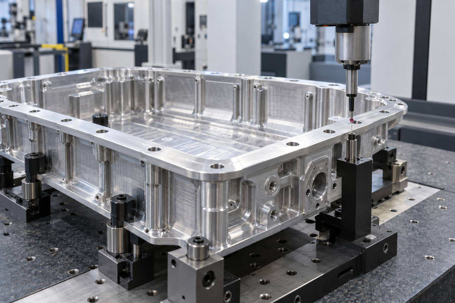
Datum strategy and sealing-surface inspection should use the same functional reference frame.
Large, thin-walled battery trays can move during roughing, heat treatment, unclamping, transport, and assembly. If the drawing defines dimensions without a functional datum structure, a supplier may produce a part that measures well in one setup but does not locate correctly in the vehicle or compress the seal consistently.
Before requesting automotive CNC machining, identify the surfaces that establish the enclosure in the vehicle and the interfaces that close the pack. Use those functions to define the datum reference frame. Mounting pads, module supports, cover flanges, connector openings, and coolant ports should then be related to that frame. Do not tighten every dimension by default. Apply close controls where variation changes sealing, alignment, electrical clearance, or load transfer, and leave non-critical stock-removal features at practical tolerances.
The sealing interface deserves its own review. Check flange flatness, local waviness, steps across joints, groove depth, corner radii, hole-to-edge distance, and tool access. Surface texture should be specified with the measurement method and direction where it affects sealing; a roughness number alone does not describe waviness, isolated scratches, or mismatch across a joint. For a machined prototype, agree whether the final sealing land will be cut in one setup, finish-machined after joining, or inspected in its assembled condition.
3. Plan the machining sequence around distortion risk
The machining plan should preserve the functional relationships established in the drawing. Removing a large amount of material from one side of aluminum stock can release residual stress and distort the tray. Thin floors, tall walls, deep pockets, and widely spaced mounting pads add sensitivity to cutting force and clamping.
A practical route often includes staged roughing, an intermediate relaxation step when justified, controlled re-clamping, and a separate finishing pass on critical features. The exact route depends on stock form, alloy temper, geometry, and available equipment. Ask the supplier to explain where material is removed first, how the part is supported, which features share a setup, and when critical flanges and bores are finished. The goal is not to prescribe every toolpath; it is to prevent a process that hides distortion until final inspection.
Inspection timing matters as much as final inspection. Measure key datums after roughing or stress-relief operations when movement is likely. Confirm sealing lands before expensive downstream work. Recheck the free-state part after it leaves the fixture, because clamping can temporarily force a flexible enclosure into tolerance. For background on process choice and multi-axis access, see the existing guide to precision CNC machining for automotive parts.
4. Treat leak testing as a controlled measurement process
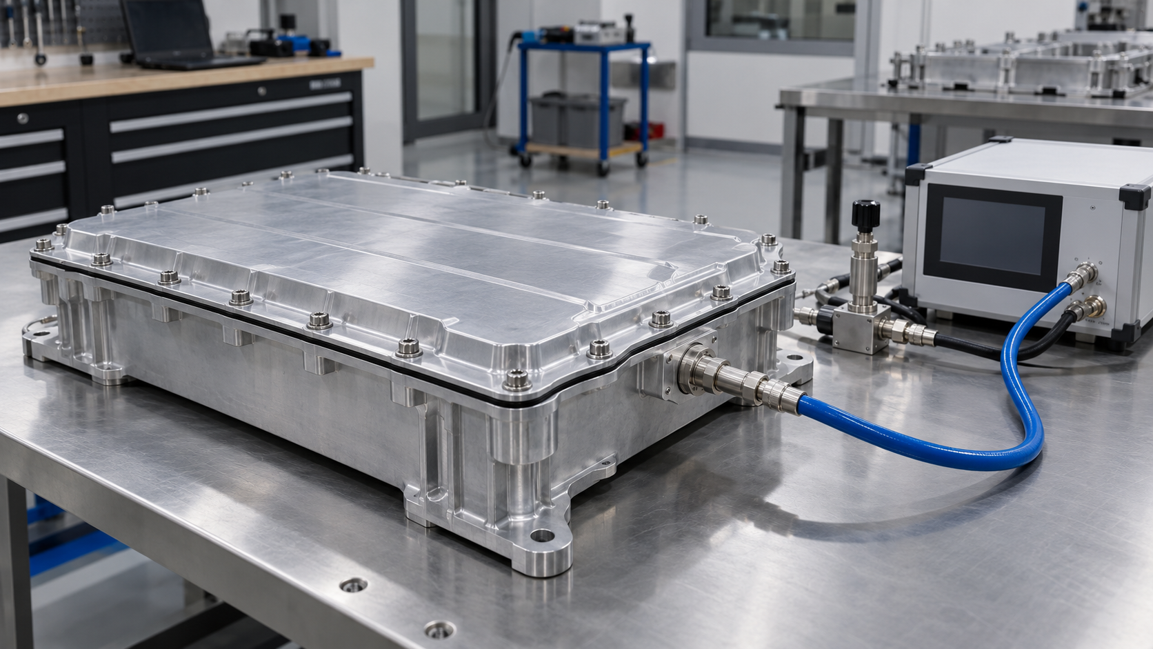
Leak-test conditions, fixtures, stabilization and acceptance limits must be recorded for repeatable evidence.
Leak testing is not one universal pass/fail operation. SAE J3277/1 distinguishes the battery-pack assembly from the coolant circuit and provides guidance for nondestructive in-line methods, system setup, tooling, validation, and the use of air or tracer-gas technologies. The correct method depends on the leakage path of concern, enclosure volume, allowable pressure, test time, sensitivity, and how the result will correlate with the functional water-ingress requirement.
| Validation question | Prototype control | Typical evidence |
|---|---|---|
| Does the cover interface seal consistently? | Representative gasket, fasteners, tightening sequence, flange condition | Recorded assembly condition and repeatable enclosure leak result |
| Is the coolant circuit isolated from the pack? | Seal all intended ports and test the circuit independently | Pressure or tracer-gas result with calibrated equipment and stated limits |
| Where is a detected leak? | Use a localization method suitable for the suspected path | Marked defect location linked to weld, casting, gasket, or fitting |
| Does the enclosure remain sealed after loading? | Repeat the same controlled leak test after the defined mechanical event | Before-and-after records using comparable conditions |
Record test pressure, medium, temperature, enclosure stabilization, fixture configuration, sensor range, calibration status, test duration, and acceptance threshold. Flexible walls can change volume under pressure, while temperature drift can look like leakage in a pressure-decay test. A result without these conditions is difficult to reproduce or compare.
Do not convert an IP requirement into an arbitrary leak-rate limit without an engineering correlation. The product team should define how the chosen production test represents the functional requirement for the specific design. Prototype trials can help establish that relationship, but the rationale belongs in the validation record.
5. Reinspect after impact, compression, or environmental loading
Recent research on localized battery-enclosure impacts emphasizes that energy absorption alone is not enough. Post-event function also includes sealing, thermal-path integrity, electrical isolation, inspection, and repairability. Another full-scale battery-pack case study combined simulation with bottom-impact and compression tests, then checked deformation and cooling-channel pressure retention. The lesson for prototype planning is straightforward: structural and sealing evidence should be connected in sequence.
Define what will be measured before the event and what will be repeated afterward. Useful checks may include datum shift, permanent deformation, cover-flange flatness, fastener torque condition, joint opening, connector alignment, coolant-circuit integrity, and the enclosure leak result. Photograph and map the impact location so inspection data can be related to the load path.
The order of tests should reflect the engineering question. If the purpose is to learn whether a bottom strike creates a leak, establish a baseline, apply the specified load, inspect for deformation, and repeat the same leak procedure. If the prototype is being used to tune a gasket or tightening sequence, complete that work before a destructive structural event. Mixing objectives can consume an expensive prototype while producing ambiguous evidence.
6. Build an inspection package that supports the next design decision
A dimensional report is most useful when it is organized around function. Mark critical-to-function characteristics on the drawing and agree on the measurement method before machining begins. A coordinate measuring machine may be appropriate for datum-related hole patterns and machined features, while large flexible surfaces may require scanning, dedicated fixtures, or a defined restraint condition. The report must state whether the enclosure was measured free, supported, or assembled.
The prototype evidence package should include:
- drawing and CAD revision identifiers;
- material grade, temper, stock form, and relevant certificates;
- manufacturing and joining route, including deviations;
- datum setup and inspection fixture description;
- results for critical dimensions and sealing surfaces;
- leak-test method, equipment, conditions, and acceptance rule;
- before-and-after records for mechanical or environmental tests;
- nonconformities, concessions, and open engineering questions.
This package creates a traceable bridge from prototype learning to the next design revision, supplier quotation, or production control plan. It also prevents a common failure: approving a design because one prototype passed, without understanding which process variables made it pass.
7. Use a staged validation checklist
A concise stage-gate checklist keeps the prototype program focused:
- Purpose defined: identify the exact design risks the prototype must reduce.
- Requirements mapped: connect vehicle and pack requirements to measurable enclosure characteristics.
- Prototype fidelity declared: document differences in material, joints, finish, hardware, and thermal components.
- Datums agreed: align machining, assembly, and inspection to the same functional reference frame.
- Sealing design reviewed: confirm flange, groove, gasket, fastener, vent, connector, and coolant interfaces.
- Process route reviewed: identify distortion risks, setup changes, and intermediate inspection points.
- Baseline recorded: complete dimensional and leak checks before structural or environmental loading.
- Post-event checks repeated: measure deformation and verify the functions that could have been degraded.
- Evidence reviewed: decide what changed, what remains uncertain, and what the next build must prove.
EV battery enclosure prototype validation works best as a chain of evidence, not a collection of unrelated tests. The drawing, machining plan, assembly method, leak procedure, structural event, and inspection report should all answer the same engineering questions. If your team is preparing a battery tray or enclosure build, contact Autoprototypes with the CAD model, critical interfaces, intended tests, and required documentation so the manufacturing and inspection plan can be reviewed before material is cut.
Article information
- Author:
- Going Rapid Engineering Team
- Published:
- Updated: