An EV battery cold plate prototype is not useful merely because coolant can pass through it. It must answer the next engineering decision: is the channel concept thermally credible, can the selected construction be sealed and measured at full scale, and does the prototype represent the risks of the intended production route?
That makes process selection a buyer decision, not a contest between CNC machining, formed sheet, brazing, welding, or metal additive manufacturing. Each route creates a different combination of geometry freedom, material fidelity, joining risk, dimensional behavior, inspection access, and transfer value. The right route depends on what the current build must prove.
Start with the decision the prototype must unlock
Define the question before requesting a quote. An early hydraulic coupon may need to compare channel pressure loss. A module-level mule may need representative ports, seals, thermal interface material, and cell loading. A production-intent plate may need the actual alloy, joining method, distortion controls, leak-test method, and inspection records. Calling all three a “cold plate prototype” hides the differences that drive cost and evidence quality.
Recent research supports this staged view. One pack-level study combined physical cooling tests with a validated CFD model to compare piped and formed aluminum layouts. Another integrated additively manufactured cold plates into a battery module and evaluated electro-thermal behavior under demanding charge and discharge conditions. Neither result means one process is universally best. Both show that useful evidence connects geometry, flow, temperature, assembly, and test conditions.
Write a one-sentence release decision for the build. For example: “select the channel family for the next module test,” “confirm that the full-size plate remains leak-tight after joining,” or “freeze the inspection plan for a supplier quotation.” That sentence becomes the filter for every manufacturing choice.
Compare routes by evidence value, not by process label
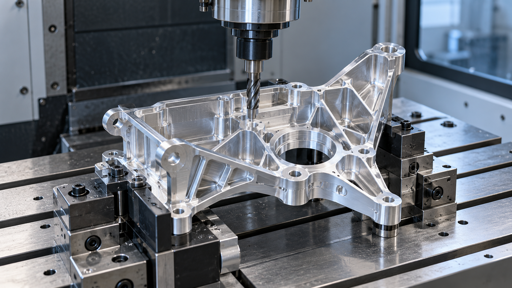
A machined plate can expose and revise channels quickly, use engineering aluminum, and provide controlled datums. It may be excellent for hydraulic or sealing learning, yet a thick machined body does not reproduce the stiffness, thermal mass, joint distortion, or thin-sheet defects of a stamped-and-brazed production design. A formed-sheet plate can improve production fidelity, but it introduces tooling, forming limits, joint preparation, furnace or weld distortion, and internal quality that may be harder to inspect.
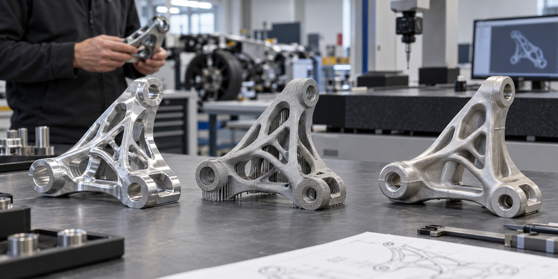
Metal additive manufacturing can create internal passages that conventional tools cannot reach and can accelerate comparison of channel concepts. It also changes surface texture, porosity risk, material condition, build orientation, post-processing, and inspection strategy. The topology-optimized copper study and the module-level aluminum study demonstrate why AM can be a powerful development route, but their measured outcomes belong to their specific materials, geometries, and test setups.
| Prototype route | Strongest learning | Main fidelity gap or risk | Evidence to request |
|---|---|---|---|
| Machined base plus cover | Fast channel iteration, datum control, ports, hydraulic tests | Mass, stiffness, seams, and thermal path may differ from production | Material state, channel inspection, cover and seal definition, free-state dimensions, pressure-loss data |
| Formed or stamped sheet plus joining | Sheet behavior, full-size distortion, seam integrity, production-like stack | Tooling and process development can dominate an early build | Forming simulation or trials, joint parameters, fixture plan, leak and NDT records |
| Metal AM | Complex internal passages, rapid geometry comparison, integrated features | Surface, porosity, build variation, and post-processing affect results | Build orientation, material condition, CT or section evidence, machining plan, hydraulic and leak results |
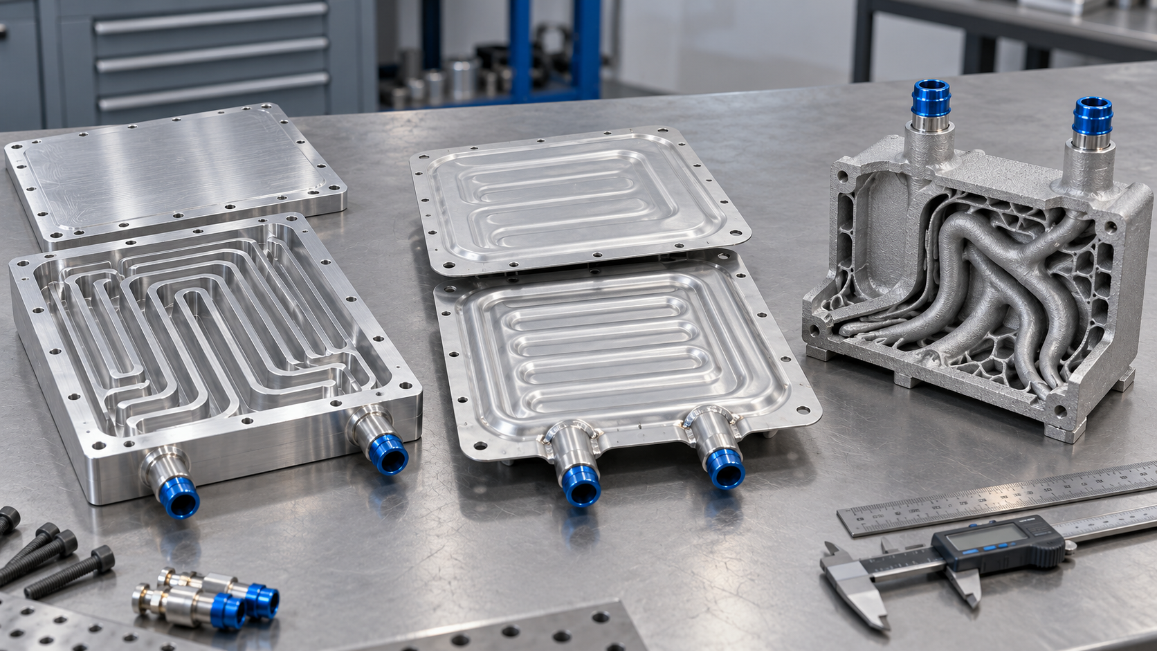 Each route answers different questions about geometry, joining, material behavior, and inspection.
Do not separate thermal design from pressure loss and interfaces
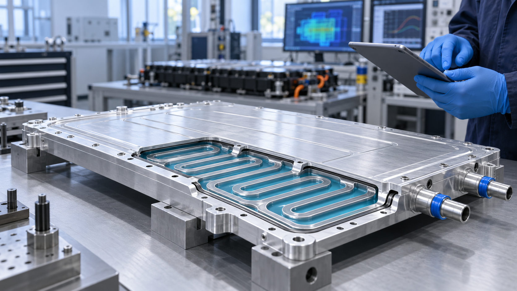
A channel that reduces a simulated peak temperature can still be a poor system choice if it produces excessive pressure loss, uneven flow distribution, difficult venting, weak port transitions, or an unrealistic thermal interface. Compare candidate plates under matched coolant, inlet temperature, flow rate, heat input, sensor placement, boundary conditions, and thermal interface material. Otherwise, the ranking may reflect the test setup rather than the geometry.
Ask for the raw conditions behind a headline result: maximum temperature, temperature spread, pressure drop, pump operating point, flow distribution, stabilization time, and uncertainty. The new Frontiers review proposes that thermal-hydraulic, production, and recovery evidence should refer to the same configuration. This is a valuable purchasing discipline. A thermal result from one model should not be combined with a leak result from another revision and a sustainability claim from a third as though they describe one qualified plate.
If the prototype is intentionally non-representative, label the gap. A clear statement such as “machined aluminum hydraulic mule; joint distortion not represented” is more useful than a vague claim of production intent.
Scale and joining can overturn a promising small prototype
Full scale changes the problem. Longer flow paths affect pressure loss. Larger thin sheets change stiffness, flatness, and fixture sensitivity. Heating and cooling during brazing or welding can move sealing lands and port locations. A joint that looks acceptable may still contain an internal defect or leak path.
AISIN’s first-party development account is instructive without being a universal specification. Its team reported that a small model did not reveal the difficulty of producing a full-scale brazed aluminum plate without leakage. The program then had to address thermal expansion, distortion, stamping cracks, repeatability, fixtures, simulation, helium leak testing, and ultrasonic inspection. The buyer lesson is not to copy their process parameters. It is to put scale, joining, and hidden-defect evidence into the prototype plan early.
For a brazed, welded, bonded, or sealed construction, define the joint stack, alloy and temper, surface preparation, filler or adhesive, fixture condition, thermal cycle, port design, and acceptance method. If a machined prototype omits the intended joint, reserve a later build specifically for joint and distortion learning.
Use three validation gates for the same revision
A practical release package can be organized into three gates. Gate one is thermal-hydraulic performance: confirm temperature behavior, uniformity, pressure loss, flow stability, and interface conditions. Gate two is manufacturing integrity: confirm material, geometry, joint quality, cleanliness, leakage, and inspection repeatability. Gate three is system and transfer relevance: confirm module fit, service connections, durability sequence, revision control, and what must change before production.
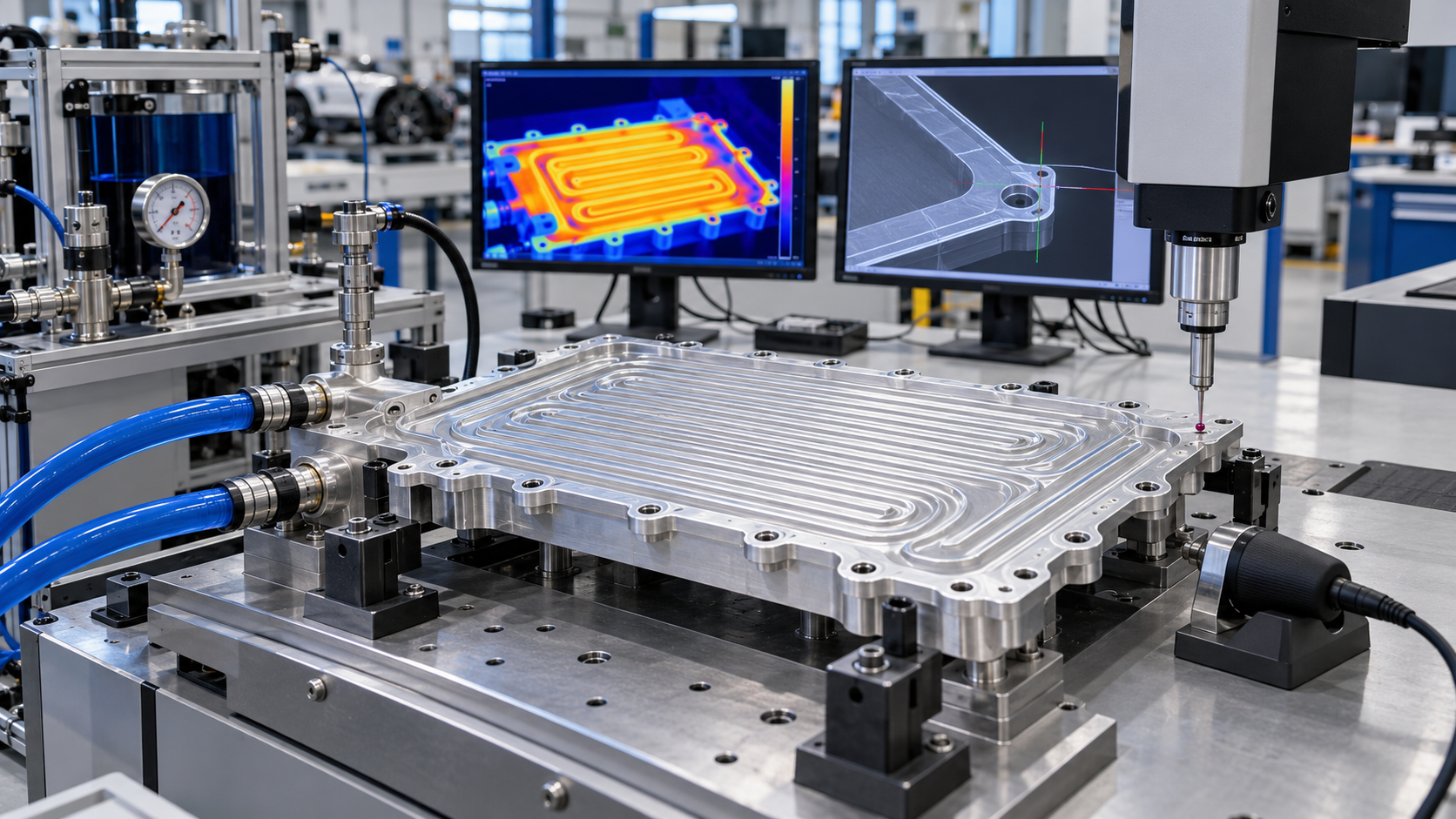 Thermal-hydraulic, manufacturing-integrity, and transfer evidence should describe the same controlled revision.
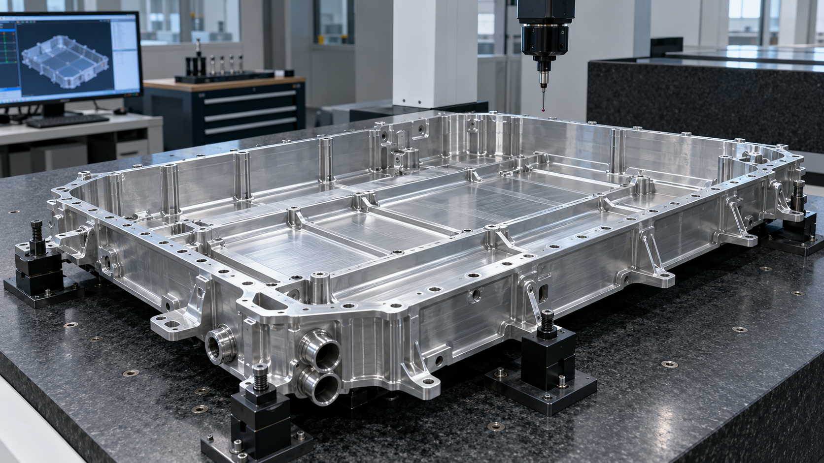
Leak testing needs a defined medium, pressure, temperature, stabilization time, fixture, sensor range, calibration status, test duration, and acceptance rule. Large flexible plates can change volume under pressure, and temperature drift can resemble leakage. Where hidden joint integrity matters, a dimensional report and a leak result may need complementary evidence such as ultrasonic inspection, radiography, CT, sectioning, or controlled destructive validation. Choose the method for the defect mode; do not request every method by default.
Keep all evidence tied to the same CAD, drawing, process route, and serial or lot identity. That traceability lets the team decide whether a failure came from the channel concept, the manufacturing process, the assembly, or the test itself.
Build an RFQ that allows suppliers to compare like with like
A useful RFQ gives suppliers enough context to propose a route without forcing an unsupported promise. Include the 3D model and controlled drawing; plate envelope and target mass; alloy and acceptable alternatives; channel concept and protected design zones; port and sealing requirements; coolant and operating range; heat-load and flow cases; maximum allowable pressure loss; critical interfaces and datums; intended quantity; prototype purpose; planned tests; required inspection outputs; and the intended production process if known.
Also identify which features may change after DFM review. A supplier can often suggest a more inspectable channel, a safer tool radius, a different cover strategy, or a staged build. For broader context on choosing among machining, AM, and casting, see the automotive lightweight prototype process-selection guide. If the plate is part of an enclosure program, the battery enclosure validation checklist helps align datums, sealing, structural events, and post-test inspection.
When machining is the selected learning route, the verified automotive CNC machining page provides a starting point for discussing materials, datums, inspection, and file formats. Company capability still must be confirmed against the actual geometry and evidence package; this article does not establish a guaranteed tolerance, lead time, capacity, or certification scope for a specific project.
Choose the minimum route that answers the next question
The best cold plate prototype is often a sequence rather than one expensive “final” build. A transparent machined or additively manufactured channel coupon can resolve flow questions. A module mule can establish interfaces and thermal instrumentation. A full-size joined plate can reveal distortion, leakage, and inspection limits. A production-intent build can then verify the controlled route.
Do not spend production-intent money to answer a basic geometry question, and do not use an easy-to-machine surrogate to approve a production joining process. Match fidelity to the decision, record the gaps, and specify the evidence needed to close them.
If you are scoping an EV battery cold plate prototype, send the CAD model, target alloy, channel concept, coolant and heat-load conditions, joining assumption, critical datums, quantity, and required tests. The next step is a manufacturability review that separates what the first build can prove from what should be reserved for the next validation gate.
Article information
- Author:
- Going Rapid Engineering Team
- Published:
- Updated: