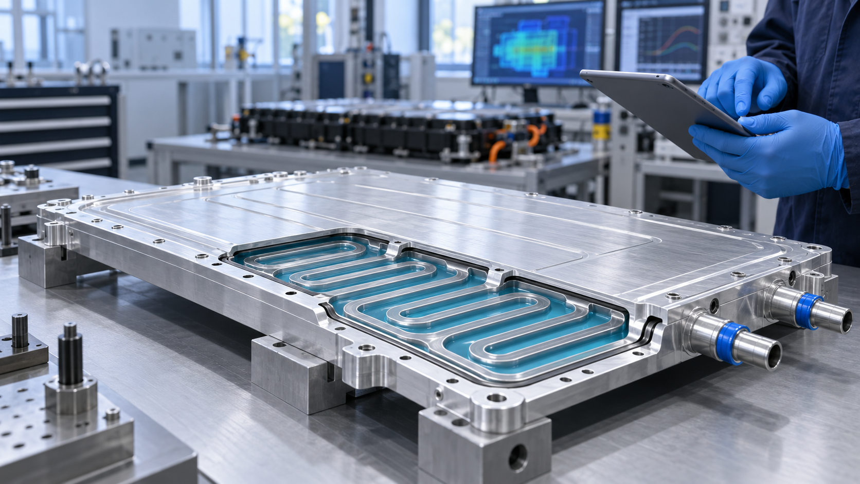
A thin-wall aluminum automotive prototype can look perfect on the machine and still miss its drawing after the clamps come off. That apparent contradiction is not necessarily an inspection mistake. The fixture, cutting force, heat, vibration, and residual stress all act on a low-stiffness structure while material is being removed. Once the part is released, those loads and constraints change, so the geometry can settle into a different shape.
This matters for battery housings, electronic enclosures, brackets, covers, fluid-management parts, and lightweight structural prototypes because their function often depends on flat sealing faces, bearing or fastener alignment, gap and flush, and repeatable assembly. The useful question is therefore not simply whether a wall can be machined. It is whether the process and inspection plan can separate temporary in-fixture shape from the free-state geometry that the vehicle team will actually assemble and test.
1. Thin walls behave like flexible structures during cutting
A thick block resists cutting loads with relatively little movement. A thin rib, web, floor, or flange has much lower local stiffness. As the cutter engages, the wall can deflect away from the tool, spring back between tooth engagements, and vibrate. The cutting edge may then remove less or more material than the programmed path implies. Local stiffness also changes continuously as pockets deepen and supporting stock disappears.
Recent experimental and modeling work on thin-wall aluminum milling confirms that force-driven deflection can be predicted only when the real wall geometry, boundary conditions, clamping, and cutting load are represented. A finite-element model can help identify a vulnerable region or compare process options, but it does not replace physical verification. Contact at supports, fixture compliance, stock variation, and tool condition can move the real process away from the model.
Automotive parts add another complication: one component may contain stiff bosses next to broad flexible walls. The same toolpath can therefore produce different error modes around the part. A dimension between two rigid bores may remain stable while a nearby sealing flange bows. Drawing reviews should flag low-stiffness regions separately instead of assigning one general machining assumption to the whole component.
2. The fixture can hide deformation as well as control it
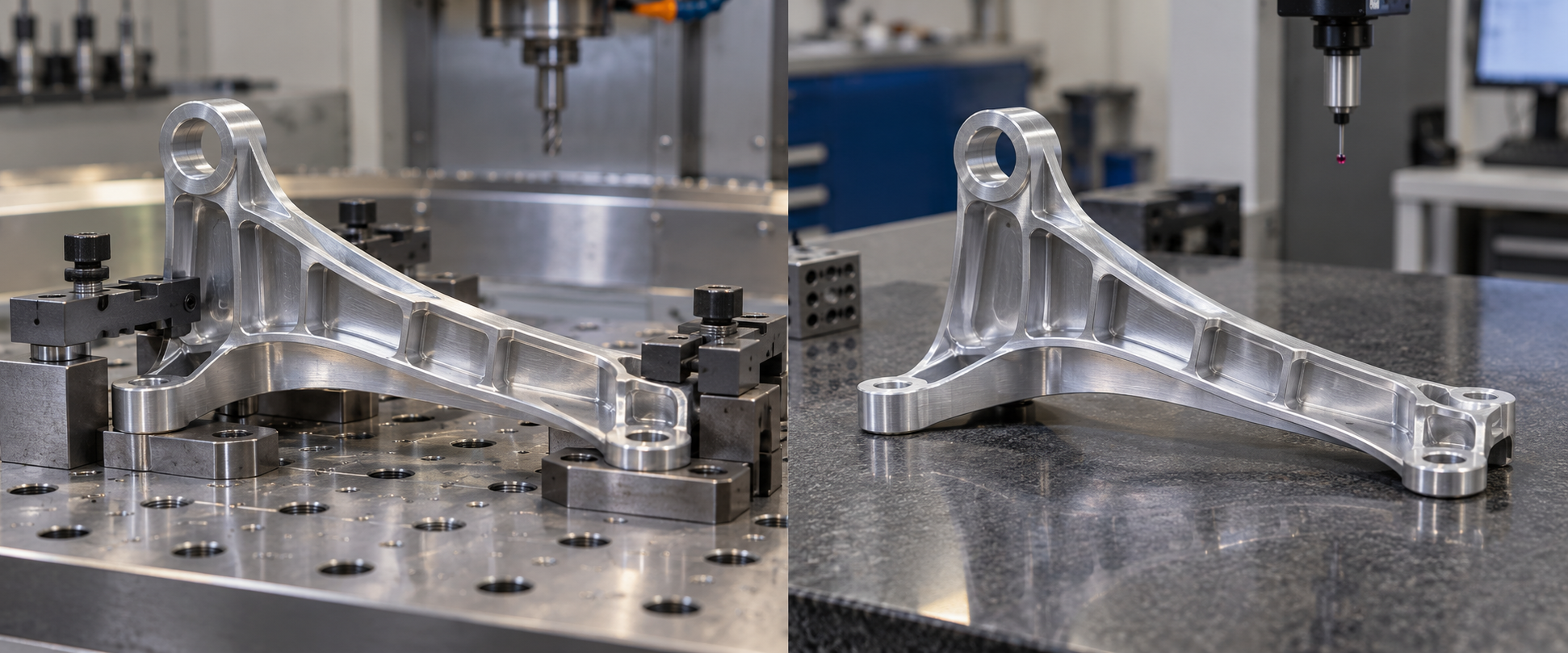
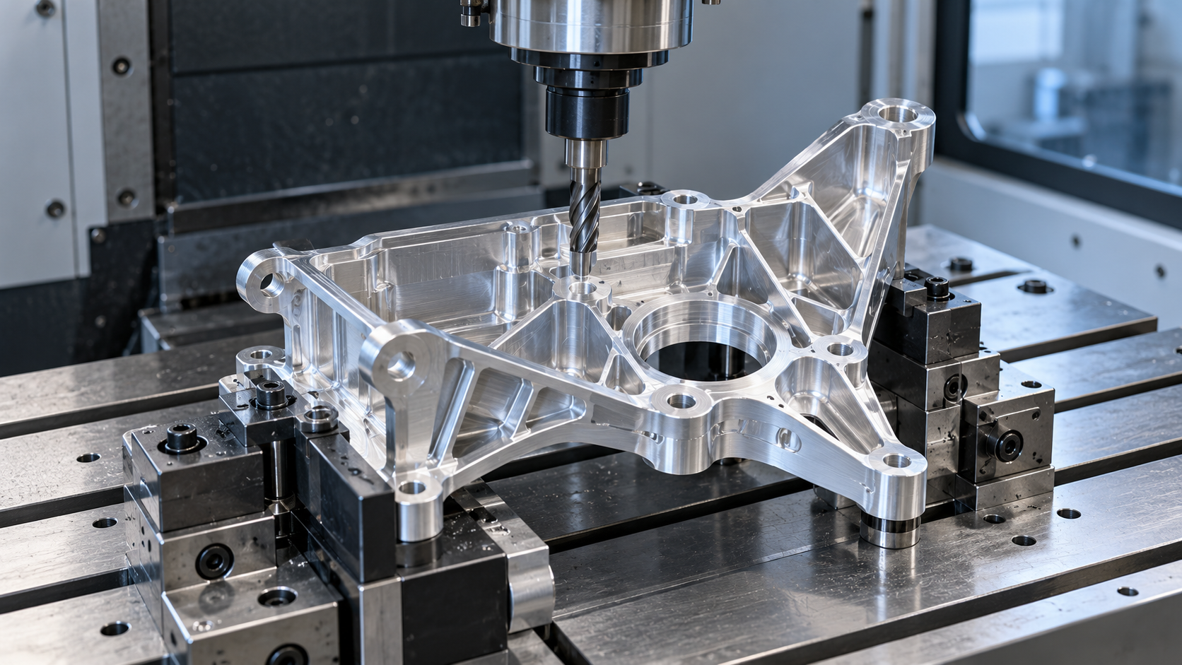
The constrained shape in a fixture is not automatically the same as the released geometry delivered for assembly.
Workholding is necessary, but it changes the structural state being measured. Clamps can flatten a bowed blank, pull a flange onto supports, or preload a wall. During machining, the constrained part may appear accurate because the fixture is forcing it into the nominal shape. When the clamps are released, elastic strain recovers and redistributed residual stress can move the part again.
This is why more clamping force is not automatically safer. Excess force can imprint or distort a thin section; too little force can allow chatter or slip. Support placement also matters. A support under a flexible floor may improve cutting stability but create a local shape that does not exist in the free part. Vacuum fixtures, soft jaws, adhesive methods, sacrificial tabs, and custom nests each alter load paths and must be assessed against the features that define function.
A sound fixture plan distinguishes location from restraint. It identifies the datum scheme, prevents rigid-body movement, supports cutting loads, and avoids unnecessary over-constraint. It should also state which dimensions may be checked in the fixture and which must be rechecked after release. If a supplier reports only on-machine probe values, the report may describe the constrained setup rather than the delivered component.
3. Residual stress changes when material is removed
Aluminum stock already contains residual stress from casting, rolling, forging, extrusion, heat treatment, quenching, straightening, and prior machining. Those internal stresses can be balanced while the blank is intact. Removing material from one region disturbs the balance. A thin part may twist, bow, or open as remaining material redistributes the stored stress.
Machining adds another layer. Mechanical loading and local heating near the cutting edge can change the near-surface stress state. Research comparing strategies in 2024-T351 and 7050-T7451 aluminum links milling strategy and cutting speed with residual stress, wall strain, flatness, chatter, and surface quality. The important lesson is not one universal parameter value. It is that material condition, tool engagement, temperature, dynamic response, and removal sequence interact.
Stock provenance therefore belongs in the prototype record. Alloy name alone is insufficient; temper, product form, blank orientation, prior stress relief, and machining history can influence distortion. If two prototypes are cut from different stock conditions, comparing their geometry without recording those differences can lead the team to blame the design or the machine for a material-state effect.
4. Toolpath symmetry does not guarantee a symmetric result
It is tempting to assume that a geometrically balanced part and a mirrored toolpath will create balanced forces. Thin-wall dynamics can break that symmetry. Entry and exit conditions differ, local support evolves, chip thickness changes, and the wall can respond at frequencies that reinforce or suppress vibration. Experimental-numerical research on AA7075 connects force, dynamic response, surface quality, and through-thickness residual stress, showing why a nominally orderly cutting pattern can still produce an asymmetric final shape.
Process planning should therefore consider roughing and finishing stock, alternating or balanced material removal, tool engagement, step-down, radial depth, cutter geometry, spindle speed, feed, and the time allowed between stages. A staged route can expose movement early: rough both sides, release or relax the part, re-establish datums, then finish critical faces. That route may be more informative than finishing one side completely while the opposite side remains a stiff mass.
Simulation, stability analysis, and prior process knowledge can narrow the parameter window, but the window should be validated on representative geometry. A simple flat coupon does not reproduce a ribbed housing with bosses, windows, and interrupted walls. For a high-risk prototype, use a witness feature or pre-production sample that preserves the stiffness and removal pattern affecting the critical interface.
5. Heat, chatter, and surface condition are connected signals
Cutting heat changes the dimensions of the tool, spindle, workpiece, and fixture while machining is underway. Thin sections respond quickly because they have low thermal mass, but temperature may not be uniform across the part. A warm part measured immediately on the machine can differ from the same part after it reaches the inspection environment. Coolant strategy, dwell time, machine warm-up, and handling therefore belong in the measurement context.
Chatter is not only a cosmetic surface problem. It signals an unstable interaction among tool, wall, fixture, and process parameters. The resulting force variation can increase deflection, change local material removal, and introduce near-surface damage. Likewise, an acceptable roughness value does not prove that flatness, wall position, or free-state shape is acceptable. Surface texture and dimensional form answer different questions.
Useful process evidence combines observations. Record chatter marks or acoustic events, inspect wall thickness and surface condition, and compare geometry at defined stages. If a part moves after release, identify whether the pattern follows clamping points, material-removal imbalance, thermal gradients, or flexible zones. That pattern is more useful for corrective action than a single pass/fail number.
6. Inspect the state that matters to assembly
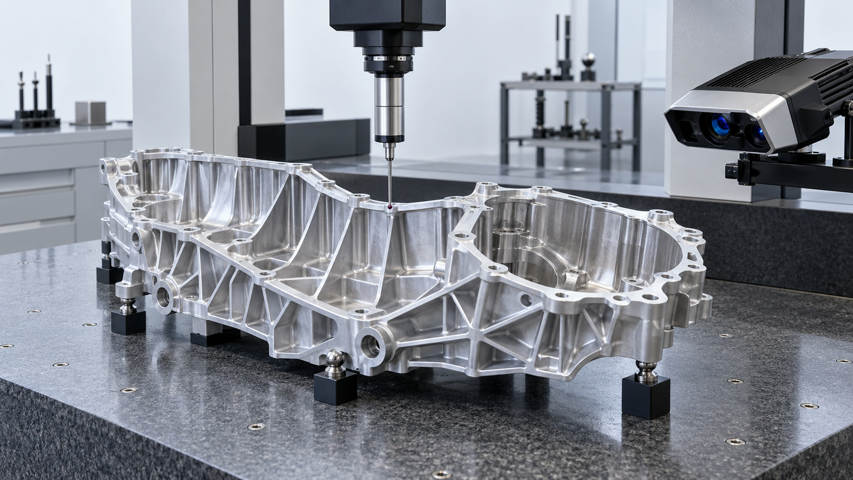
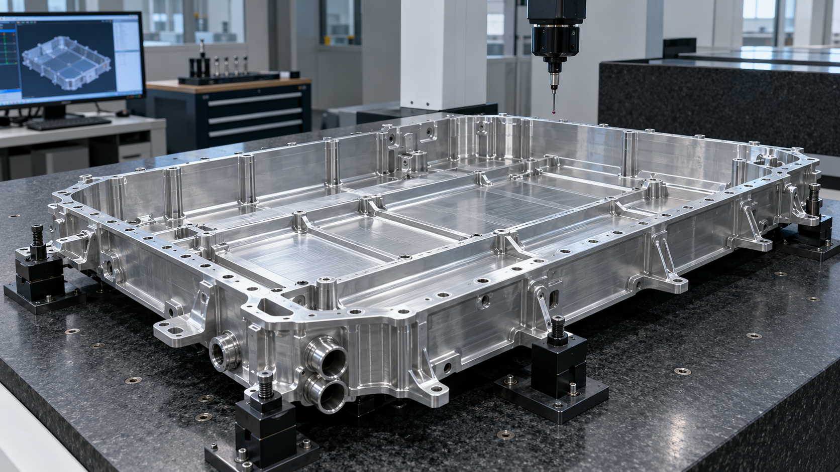
Free-state inspection should use defined supports, datums, environment, and stabilization time.
Define inspection states before the RFQ. At minimum, distinguish in-process checks, immediate post-release checks, and stabilized free-state inspection. State the support method, datum simulation, environmental condition, and elapsed time when they can influence results. For a sealing flange or assembly interface, specify whether the requirement applies in free state, under a defined assembly load, or both.
Use measurement methods appropriate to the feature. A CMM can capture datums, bore relationships, profiles, and flatness with a controlled setup. Optical scanning can reveal broad shape changes and compare deformation fields, but reflective surfaces, alignment strategy, and uncertainty need control. On-machine probing is valuable for process adjustment, yet it cannot by itself prove the released geometry. Functional gauges or assembly fixtures can add evidence when interface behavior matters more than isolated coordinates.
The inspection drawing should avoid ambiguous restraint. If technicians must press a flexible part onto a surface to establish a datum, the procedure may mask the very distortion being evaluated. Define minimal supports or a specified fixture force, and report both raw free-state behavior and any assembly-constrained result needed by engineering. The goal is traceable evidence, not an artificially good number.
7. Turn distortion risk into a controlled prototype plan
Before requesting an automotive CNC prototype, provide the CAD model, controlled drawing, alloy and temper, product form, blank orientation if relevant, target quantity, critical interfaces, intended assembly restraint, and inspection state. Mark walls, floors, ribs, and flanges whose free-state position affects sealing, fit, load transfer, or vehicle appearance. Explain which features can accept a process change and which cannot.
Ask the manufacturing review to return the proposed stock condition, datum and fixture concept, roughing and finishing sequence, stress-relief or relaxation stages if any, machining allowance, tool-access constraints, and inspection plan. Request explicit identification of measurements taken in the fixture versus after release. This turns thin-wall distortion from a late surprise into a shared engineering variable.
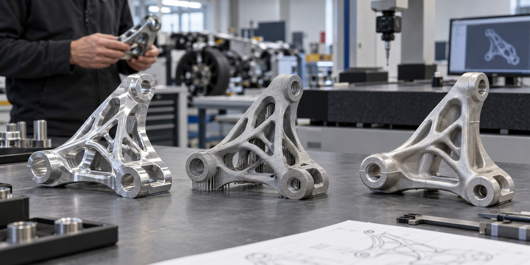
Autoprototypes' broader automotive manufacturing services can be used to compare CNC machining with alternate prototype routes when geometry becomes too flexible or when production-process fidelity matters more than billet accuracy. A thicker temporary wall, sacrificial support, split build, casting route, or additive preform may sometimes produce better evidence than forcing the original billet strategy.
To scope a thin-wall aluminum prototype, send the engineering team the model, drawing, material condition, critical free-state features, assembly constraints, and required inspection evidence. The next step is a manufacturability review that identifies distortion drivers, proposes a machining and release sequence, and defines which dimensions must be verified after the part has left the fixture. No universal parameter or guaranteed tolerance is implied; the plan must be validated for the actual geometry and stock.
Article information
- Author:
- Going Rapid Engineering Team
- Published:
- Updated: